How LLMs and AI is Changing the Design to Build Workflow

This article is a deeper look at how AI handles CAD generation, floorplan and layout recognition, materials estimation, and quantities takeoffs. While LLMs have excellent capabilities there are some areas where these models have some disadvantages as compared to traditional human analysis of plans and CAD files.
In the first article in this series, we mapped the broad terrain of how AI is used for generating chip layouts, discovering novel materials, navigating drones in real time, and compressing engineering iteration cycles. In this article we explore the design applications for LLMs / AI in more detail.
The most consequential — and least discussed — applications of AI in industrial design are not the headline-grabbing ones, they are the initoial decisions that determine whether a product can be manufactured at all, at what cost and with what materials. Floorplan recognition, materials estimation, and quantities takeoff are very functional tasks that can consume lots of human hours and are prone to errors. These tasks are, however, the part of the design process where the most capital is routinely misspent, and where AI is now producing the most measurable returns.
I analyse different elements or layers of the CAD design workflow and how AI is playing in these different areas.
The Four-Layer Design Stack
Layer 1 — Generative design and CAD. AI proposes geometry. Given constraints — loads, materials, manufacturing method, cost target — the model generates candidate designs rather than waiting for a human to sketch them. This is the most visible layer: the organic brackets and latticed structures that look like nothing a human would draw.
Layer 2 — Layout and floorplan recognition. AI reads existing drawings such as 2-dimensional PDFs, scanned blueprints, CAD files, chip layout files and extracts structured data from them. Walls, room sizes, functional zones, circuit blocks, routing channels. The LLM parses the image and extracts geometric information, it is this is the layer that enables every downstream automation.
Layer 3 — Materials estimation. Given a design or a recognised floorplan, AI predicts what materials will be required and in what quantities. LLMs are pretty good at estimating the physical quantities based on reference information. In some pipelines this feeds directly into procurement and in others it feeds into simulations to verify that the specified materials will survive the likely operating conditions (this can be calculated from known fatigue points of materials).
Layer 4 — Quantities takeoff. The automated generation of Bills of Quantities (BOQ) or Bills of Materials (BOM) which is an itemised list of every component, material, fastener and sub-assembly required to build the designed object or construction project. Traditionally this took weeks of manual counting and measuring, whereas AI now does it in hours, with higher accuracy than human estimators working from the same drawings (although this is dependent on the LLM seeing the CAD drawing properly and measuring the dimensions correctly in the first place).
A startup that is creating products or in the building industry can in theory now use LLMs to automate all four layers which creates a design-to-manufacture pipeline that is structurally faster and cheaper than any human only incumbent. There are caveats in terms of LLMs ability to generate the same answer every time in runs and the issue with LLMs hallucinating which is a common problem.
01 — Semiconductors: The Most Mature AI Design Stack
The semiconductor industry is where AI-assisted design is furthest advanced and it is a useful benchmark for what other manufacturing sectors is moving towards.
CAD and Generative Layout
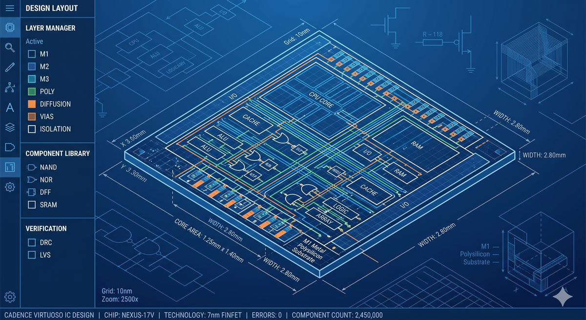
Chip design is fundamentally a spatial optimisation problem. A modern System-on-Chip (SoC) contains billions of transistors that must be placed and connected within a die area measured in square millimetres, under simultaneous constraints on performance, power consumption, thermal behaviour, and signal integrity and at advanced nodes below 5nm, the complexity has outrun what human designers can optimise manually.
Floorplanning is where AI has made its most dramatic intervention for example Google DeepMind's AlphaChip which was published in Nature in 2021 posed chip floorplanning as a reinforcement learning problem. An edge-based graph convolutional network (what a mouthfull!) learned representations of the chip's logic graph, then an RL agent used those representations to place macro blocks (which is the memory, processing units and IP blocks) on the die. The result was floorplans generated in under six hours that were superior or comparable to human experts across power, performance, and surface area. Designs that previously took physical human teams, months of iteration arrived in a single working day!
What makes this technically significant beyond the headline is the transfer learning component. The trained agent performs better on a new chip design after having seen previous ones — the model accumulates design intelligence across projects, which human designers cannot do at the same scale. Each new chip makes the agent better at the next one.
Synopsys DSO.ai and Cadence Cerebrus have since commercialised the same RL-driven approach inside their respective EDA toolchains. Synopsys's IC Compiler II uses ML-driven macro placement that predicts design metrics — congestion, wirelength, timing — and explores hundreds of floorplan options before presenting the engineer with a ranked shortlist. Cadence Cerebrus applies reinforcement learning across the entire implementation flow, not just placement, optimising PPA (Power, Performance, Area) metrics end to end without requiring engineers to manually tune each stage.
Materials Estimation in Semiconductor Design
Materials choices in chip design operate at the atomic scale including gate dielectric materials, interconnect metals, substrate composition, and packaging substrates. All of these interact with each other in ways that are difficult to simulate using manual human driven methods.
Graph neural networks (specifically SchNet-class models and their successors) trained on the Materials Project database can predict dielectric constants, thermal conductivity, electron mobility, and oxidation resistance for candidate materials before a single wafer is processed. This is used in practice to pre-screen hundreds of candidate gate dielectric materials and select the most promising two or three for physical fabrication trials, compressing materials qualification cycles significantly.
At the packaging level — where advanced 3D stacking and chiplet integration requires careful management of thermal expansion mismatch between different materials — physics-informed neural networks (PINNs) are being used as surrogate models for finite element thermal analysis, running orders of magnitude faster than traditional COMSOL or Ansys simulations.
Quantities Takeoff
In semiconductor manufacturing, the equivalent of quantities takeoff is a process bill of materials generation — the specification of every chemical, gas, target material, and consumable required to run a fabrication process. This includes photoresist formulations, etch chemistries, deposition precursors, and cleaning solvents, all of which must be planned, ordered, and qualified before wafer processing begins.
AI tools embedded in manufacturing execution systems (MES) now automate process BOM generation from design rule files and process flow specifications. Large language models are particularly useful here for parsing legacy process documentation — foundries like TSMC and Samsung have process design kits (PDKs) that are thousands of pages of technical documentation. LLMs can extract the relevant specifications for a new design without requiring engineers to read every document manually.
Best model fits:
● Floorplanning and placement → Deep RL (PPO, graph convolutional networks as policy networks)
● Materials property prediction → Graph neural networks (SchNet, MEGNet, MatDeepLearn)
● Thermal simulation surrogate → Physics-informed neural networks (PINNs, Fourier Neural Operators)
● Process documentation parsing → Large language models (Claude 3.5 Sonnet, GPT-4o with structured output)
● Commercial tools → Synopsys DSO.ai, Cadence Cerebrus, Ansys Mechanical with ML extensions
02 — Aerospace and Drone Manufacturing: Weight Is Money
In aerospace engineering and design every gram of material that can be removed from a structure without compromising structural strength directly reduces fuel consumption. For drones specifically, weight determines payload capacity, flight time, and range. The economic incentive to use AI for design optimisation is direct, for example a 10% weight reduction in a commercial UAV frame translates to a measurable increase in commercial utility (such as range or payload capacity) and and therefore market value of the drone.
Generative CAD for Structural Components
Autodesk Fusion's generative design workspace is the most widely used commercial tool for this application. The engineer defines: the space the part must fit within, the load cases it must survive (directions and magnitudes of forces), the materials available, and the manufacturing method constraints (additive only, or also subtraction, die casting, etc.). The software then runs topology optimisation across hundreds of geometry candidates and returns a ranked set of designs, each satisfying the structural requirements with different trade-offs between weight, stiffness, and manufacturability.
The outputs are famously organic — latticed, branched structures that resemble bone more than machined metal. This is not aesthetic choice; it is the mathematically optimal way to route material only along the paths where stress actually flows. Boeing, Airbus, and numerous UAV manufacturers use this approach for brackets, fittings, and non-standard structural connectors.
ANSYS Discovery sits alongside this as a real-time physics validation layer. Where Autodesk generates geometry candidates, Ansys validates them — running FEA and CFD simulations on modified designs in real time as engineers adjust parameters. The traditional workflow separated these stages by days; Discovery collapses them to seconds by using GPU-accelerated approximate solvers that sacrifice some numerical precision for speed. For early-stage design decisions, where the goal is to eliminate bad options rather than certify good ones, this trade-off is almost always worth making.
For drone airframe design specifically, Neural Concept's deep learning CFD surrogate model approach is worth understanding. Rather than running a full computational fluid dynamics simulation for every candidate geometry — which takes hours on a cluster — a neural network trained on thousands of prior CFD results predicts aerodynamic performance (drag, lift distribution, pressure coefficients) for a new geometry in seconds. The model does not replace CFD certification; it replaces the preliminary exploration phase, which is where most engineering time was previously spent.
Floorplan Recognition for Manufacturing Layouts
When a drone manufacturer is designing or expanding a production facility, the "floorplan recognition" problem becomes factory layout optimization. So given a building footprint and a set of production processes, how should the floor space be allocated to minimise material handling distance, ensure ergonomic flow and meet regulatory clearance requirements?
AI tools applied to factory floor plans, uploaded as PDFs or CAD files, can extract room geometry, identify existing fixed infrastructure (columns, utilities, loading docks), and then run optimisation models to propose equipment placement. This sits at the intersection of computer vision (reading the drawing) and operations research (optimising the layout).
For drone assembly specifically, where the production flow moves from composite layup through CNC machining to electronics integration and final test, the sequencing of these stations and the buffer sizes between them are critical determinants of throughput and working capital requirements. Digital twin platforms from Siemens (Tecnomatix Plant Simulation) and Dassault Systèmes (DELMIA) are now incorporating ML-based optimisation engines that can propose layout alternatives and simulate their throughput performance before a single piece of equipment is moved.
Materials Estimation for Composite Structures
Drone airframes are predominantly carbon fibre reinforced polymer (CFRP) composites. Materials estimation for composites is significantly more complex than for metals: the material properties are anisotropic (different in different directions), depend on the layup sequence (the order and orientation of plies), and are sensitive to the cure cycle. Getting materials estimation wrong results in either structural failure or unnecessary mass.
AI approaches to composite materials estimation typically involve surrogate models trained on classical laminate theory calculations combined with experimental data. Given a target structural performance (stiffness, failure load, natural frequency), the model predicts the optimal ply layup — number of plies, orientations, and stacking sequence — and from that derives the materials quantities. This automates what was previously several days of manual laminate analysis.
Quantities takeoff for composite assemblies then flows directly from the ply schedule: each ply has a defined shape, area, and fibre orientation, which translates directly to a cutting plan and a material quantity. AI-driven nesting optimisation (the same class of problem as sheet metal nesting) then minimises material waste by optimally arranging the cut ply shapes on the raw fabric roll — a problem that is provably NP-hard but tractable via heuristic ML approaches that consistently outperform human layout by 8–15% material utilisation.
Best model fits:
● Structural generative design → Topology optimisation with gradient-based solvers (SIMP method, embedded in Fusion/Ansys)
● Aerodynamic surrogate → Convolutional neural networks on geometry meshes (Neural Concept, NVIDIA Modulus)
● Factory layout optimisation → Genetic algorithms and RL-based optimisation (Siemens Tecnomatix)
● Composite ply estimation → Physics-informed surrogate models trained on classical laminate theory data
● Nesting and cutting optimisation → Heuristic ML (beam search, simulated annealing with learned cost functions)
● Commercial tools → Autodesk Fusion Generative, Ansys Discovery, Neural Concept, CATIA Composites (Dassault)
03 — Industrial Machinery and Micro-Factories: Designing the Factory That Builds the Factory
This is the most intellectually interesting application of the design AI stack, and the one most directly relevant to Reindustri's thesis about micro-factories. The question is: can AI automate not just the design of individual machines, but the design of the factory system that produces them?
Floorplan Recognition at Industrial Scale
When a founder is setting up a manufacturing operation — whether a CNC machining cell, a PCB assembly line, or a micro-factory for drone components — they typically start with a building floor plan (usually a PDF from a property agent or landlord) and a list of machines they need to accommodate. Translating that into a detailed facility layout has traditionally required a specialist industrial engineer and several weeks of work.
Floorplan recognition AI now extracts structured geometry from these PDFs automatically. The pipeline typically runs as follows:
First, a computer vision model (fine-tuned Vision Transformer or a dedicated architectural drawing model) segments the PDF into semantic layers — walls, doors, windows, structural columns, utility points. This is harder than it sounds: engineering drawings use conventions that differ between countries, decades, and drawing offices, and the model must generalise across them. The leading commercial tools doing this — Kreo, Reconstruct, and PlanSwift AI — have trained on millions of architectural and industrial drawings to achieve the generalisation required.
Second, the recognised geometry is converted into a graph representation: rooms are nodes, openings are edges, and spatial relationships (adjacency, visibility, clearance) become graph properties. This structured representation is then queryable — you can ask "where are the column centrelines?" or "what is the total area of zones with 3-phase power access?" — in ways that were impossible from a raw PDF.
Third, an optimisation model (typically a constraint satisfaction or RL-based planner) proposes equipment placement within the recognised geometry, subject to constraints on clearance, material flow, utility access, and ergonomics. The output is a proposed factory layout, annotated with flow paths and key metrics, that a human engineer reviews and refines.
The productivity gain is substantial. Kreo's published data on construction quantity takeoff — the direct analogue of this process applied to building projects — reports a 13.5x speed improvement over manual methods with higher accuracy.
Quantities Takeoff for Machine Build
When a startup is building or procuring a custom machine — a CNC gantry, a laser cutter, an automated assembly fixture — the Bill of Materials is the first major financial commitment. Getting it wrong means either re-ordering components (delaying the build) or over-ordering (wasting capital). For a micro-factory founder working with a tight budget, BOM errors are not just inconvenient; they are existential.
AI quantities takeoff applied to machine design works as follows. The engineer's CAD model (in Fusion, SolidWorks, or Onshape) is parsed by a BOM extraction tool that reads every component from the assembly tree, identifies purchased parts versus manufactured parts, and links purchased parts to supplier catalogues to generate current pricing. This is essentially solved for standard CAD workflows — most modern PDM systems do it automatically.
The more interesting problem is early-stage BOM estimation, where the CAD model does not yet exist. Given a functional specification ("a 3-axis CNC router with 1200×800mm work area, 5kW spindle, and ±0.05mm positioning accuracy"), can AI estimate the major cost components before detailed design begins?
Large language models with access to engineering databases and supplier catalogues can do a reasonable job of this at the system level — estimating the frame, linear motion, spindle, controller, and enclosure costs to within ±20–30% of actual. This is sufficient for early business case analysis. For detailed BOM generation, the LLM output needs to be validated against actual CAD, but having a rough estimate in hours rather than weeks changes the economics of early-stage decision-making for founders.
Materials Estimation for Factory Infrastructure
When designing a new production facility, materials estimation covers a broader scope than just the machines: structural modifications, electrical infrastructure, compressed air systems, dust extraction, fire suppression, and floor loading upgrades all have materials and quantities associated with them.
This is where the construction industry's quantities takeoff tools become directly relevant to manufacturing founders. Platforms like Kreo (UK-based, construction-focused but applicable to industrial fit-outs), PlanSwift, and Procore's AI estimation tools can read architectural drawings of a proposed facility and automatically generate:
● Structural steel quantities (columns, beams, brackets)
● Electrical conduit and cable lengths by circuit type
● Ductwork lengths and areas for ventilation systems
● Concrete volumes for equipment plinths and trenches
● Wall cladding areas for clean room or explosion-proof zones
The underlying technique is floor plan recognition combined with rule-based quantity extraction. The AI reads the drawing, identifies element types (a dashed line with a specific symbol means ductwork; a solid rectangle with hatching means concrete), measures their dimensions from the drawing scale, and accumulates totals by category. NLP components then read the specification notes and legends alongside the drawing to correctly classify ambiguous elements.
The models that perform best at this task are fine-tuned vision transformers (ViT or DINOv2-class) for the drawing recognition step, combined with rule-based extractors for the measurement calculation step. The RL and generative approaches that work well for geometry creation are less appropriate here — this is a recognition and measurement task, not an optimisation task, and the best models are those trained on the largest and most diverse corpora of actual engineering drawings.
Best model fits:
● Floorplan geometry extraction → Fine-tuned Vision Transformers (ViT-B/16, DINOv2), specialised architectural drawing models
● Factory layout optimisation → Constraint programming + RL (Siemens Tecnomatix, custom OR-Tools implementations)
● Early-stage BOM estimation → Large language models with structured output and tool use (GPT-4o, Claude 3.5 with function calling to supplier APIs)
● Detailed quantities takeoff → Computer vision + rule-based measurement (Kreo, PlanSwift AI, Procore Estimation)
● Machine BOM extraction → PLM-integrated tools (SolidWorks BOM, Onshape Release Management)
● Commercial tools → Kreo, PlanSwift, Autodesk Takeoff, Procore, custom pipelines on DINOv2
04 — Engine and Turbine Design: Where Physics Still Dominates
Turbomachinery is one of the most demanding design domains in manufacturing. A gas turbine blade operates at temperatures exceeding the melting point of the base metal it is made from (sustained only by internal cooling channels and thermal barrier coatings), under centrifugal loads equivalent to hanging a London double-decker bus from the tip of your finger, at rotational speeds above 10,000 RPM. The tolerance on blade geometry is measured in microns. Getting it wrong does not produce a suboptimal product; it produces a catastrophic failure.
This is a domain where AI augments but does not replace physics-based simulation — and understanding why is important for founders and investors evaluating AI claims in high-consequence engineering.
Generative Design for Turbomachinery
The geometry of turbine blades and compressor aerofoils is among the most optimised of any engineering component, refined over decades of both empirical testing and computational optimisation. AI generative design enters here not by proposing completely novel geometries from scratch (the physics constraints are too tight for unconstrained exploration to be useful), but by automating parametric exploration within the established design space.
Ansys Mechanical combined with Ansys optiSLang runs design of experiments and surrogate-model-based optimisation: instead of evaluating every point in the design parameter space with a full CFD or FEA solve, a Gaussian process or neural network surrogate model is trained on a sparse initial sample of evaluations, then used to predict the performance at unsampled points and guide the search toward the optimum. This reduces the number of expensive full simulations required by an order of magnitude.
For the internal cooling channel geometry of turbine blades — a three-dimensional network of passages that must transfer maximum heat with minimum pressure drop — topology optimisation approaches (similar in principle to structural topology optimisation used in aerospace) are being applied to find channel geometries that human designers would not intuit.
Materials Estimation for High-Temperature Applications
The materials used in hot-section turbomachinery — nickel superalloys, ceramic thermal barrier coatings, single-crystal directionally solidified metals — are among the most expensive engineering materials by weight. Materials estimation at the design stage directly drives cost forecasting and supply chain planning.
AI approaches here draw on physics-informed neural networks trained on both experimental creep, fatigue, and oxidation data and thermodynamic modelling (using tools like Thermo-Calc for phase diagram calculation). Given a candidate alloy composition and a set of operating conditions (temperature cycle, stress amplitude, environment), the model predicts life-limiting properties — creep rupture life, high-cycle fatigue strength, oxidation rate — that are the key inputs to materials selection decisions.
This is genuinely difficult. The training data is expensive to generate (each data point requires a physical test specimen and hundreds or thousands of hours of test time), the physics is complex, and the extrapolation risk is high. The best current practice is to use the AI surrogate to screen large alloy composition spaces down to a shortlist, which is then validated experimentally — the AI compresses the experimental programme, not eliminates it.
Quantities Takeoff in Engine Manufacturing
Engine bills of materials are famously complex — a large commercial jet engine contains tens of thousands of individual parts. AI-assisted BOM management in this context focuses less on initial quantity estimation (the design drives the BOM precisely) and more on:
Change impact analysis. When a design change is proposed — a modification to a compressor stage, a material substitution in a combustor liner — LLMs combined with PLM graph representations can automatically identify every downstream part affected by the change, the lead times for re-qualifying suppliers, and the estimated cost impact. This used to require a team of configuration engineers working for weeks; the AI can generate a first-cut impact assessment in hours.
Supply chain quantities estimation. Given a production rate plan ("500 engines per year") and the BOM, AI tools now forecast component demand at the sub-tier supplier level, flagging potential bottlenecks where a single supplier is the source for multiple critical parts. This is a graph problem — the BOM is a directed acyclic graph — and graph neural networks are well-suited to it.
Best model fits:
● Parametric aerofoil optimisation → Gaussian process surrogates, Bayesian optimisation (Ansys optiSLang, Dakota)
● Materials property prediction for superalloys → Physics-informed neural networks with thermodynamic integration
● Topology optimisation of cooling channels → Adjoint-based methods with ML surrogate acceleration
● BOM change impact analysis → LLMs with structured PLM graph context (GPT-4o, Claude 3.5 with tool use)
● Supply chain demand forecasting → Graph neural networks on BOM graph (custom GNN implementations)
● Commercial tools → Ansys Mechanical + optiSLang, Siemens NX + Teamcenter, PTC Windchill
05 — 3D Printing and Additive Manufacturing: Design for the Process
Additive manufacturing is the one domain where AI generative design and AI process planning are genuinely inseparable — because the design and the manufacturing process are not independent. The geometry of a 3D printed part determines the print strategy, the support structure requirements, the print time, and the material consumption, which in turn determine the cost. You cannot finalise the design without understanding the process, and you cannot plan the process without the finalised design.
Generative Design Constrained by Print Process
The key differentiator of AI-assisted design for additive manufacturing is the inclusion of manufacturability constraints specific to the printing process: overhang angle limits (geometry that would require support structures), minimum feature size, build orientation, and residual stress accumulation during the build.
Tools like nTopology (which operates on implicit geometry rather than traditional boundary representation solid models) are designed specifically for this. The geometry is defined as a mathematical function rather than a set of surfaces, which allows arbitrary complexity — fine lattice structures, graded density regions, conformal cooling channels — that would be impractical or impossible to create in traditional CAD. The AI layer within nTopology allows the engineer to define performance targets (thermal performance, structural stiffness, weight limit) and have the system explore the implicit geometry space to find solutions that meet them.
Autodesk Netfabb takes a different approach, operating on the manufacturing planning side: given a 3D model intended for additive manufacture, Netfabb's AI analyses the geometry and automatically proposes build orientation, support structure strategy, and process parameters, then generates the estimated print time and material consumption — which is the additive manufacturing equivalent of quantities takeoff.
Materials Estimation and Quantities Takeoff for Additive
The quantities takeoff problem for additive manufacturing has a deceptively simple answer at the top level: the material consumed is the volume of the part plus the volume of the support structures, divided by the packing density of the powder or filament. In practice, it is considerably more complex.
Support structure volume can vary by an order of magnitude depending on build orientation — a part printed vertically might require 5% support material; the same part printed at 45 degrees might require 50%. AI optimisation of build orientation to minimise support material, while also considering thermal distortion and surface finish requirements, directly determines material cost.
For metal powder bed fusion processes (SLM, DMLS), the powder consumption per build is not simply the part volume — it includes the powder in the surrounding unfused volume, which has a utilisation rate that varies with machine model, part geometry, and nesting density. AI nesting tools (analogous to the sheet metal nesting tools mentioned in the aerospace section) optimise the arrangement of multiple parts within a single build volume to maximise machine utilisation and minimise cost per part.
The leading commercial tool here is Materialise Magics, which includes AI-based support generation, orientation optimisation, and build nesting, producing a materials and time estimate as an output of the process planning step.
Best model fits:
● Generative design for additive → Topology optimisation on implicit geometry (nTopology, Autodesk Fusion)
● Build orientation and support optimisation → Multi-objective RL or evolutionary algorithms (Materialise Magics, Autodesk Netfabb)
● Print process parameter prediction → Convolutional neural networks on layer images + thermal models
● Quantities takeoff for additive → Geometric calculation engines with AI-optimised nesting (Materialise Magics, 3DXpert)
● Commercial tools → nTopology, Materialise Magics, Autodesk Netfabb, 3DXpert (3D Systems)
The Model Selection Framework
The consistent pattern across all five industries is that different stages of the design stack favour different model architectures — and using the wrong model type for a given task produces poor results regardless of how well it is implemented.
When to use reinforcement learning: Placement and routing problems with discrete action spaces and evaluable outcomes (chip floorplanning, factory layout, build nesting). RL excels when the solution space is too large for exhaustive search and when the performance of a candidate solution can be rapidly evaluated by simulation.
When to use graph neural networks: Any problem that is naturally represented as a graph — molecular structure, BOM hierarchy, supply chain networks, chip netlists. GNNs respect the relational structure of these problems in a way that flat neural networks do not.
When to use physics-informed neural networks: Surrogate models for physical simulation where training data is expensive to generate and the underlying physics provides a strong prior. Turbine thermal analysis, semiconductor process simulation, composite cure modelling.
When to use vision transformers: Drawing recognition, defect detection, geometry understanding from images. ViT and DINOv2 outperform CNNs on tasks with small training datasets due to better transfer learning from large pre-training corpora — which describes most industrial vision tasks.
When to use large language models: Documentation parsing, BOM change impact analysis, early-stage estimation from natural language specifications, cross-system workflow automation. LLMs are the connective tissue of the industrial AI stack, not the specialist solver — they translate between domains and synthesise information, but they should not be asked to do physics they were not trained for.
When to use Gaussian process surrogates and Bayesian optimisation: Parametric design space exploration where each function evaluation is expensive (CFD, FEA) and the dimensionality is moderate (tens of design variables). The gold standard for turbomachinery and aerospace aerodynamic optimisation.
What This Means for Founders
The design stack using LLMs and AI described above is not theoretical as all of the tools and model approaches mentioned here are commercially available and in active use at scale. What is new is the accessibility as most of these tools are now within reach of individuals and startups.
The strategic implication is specific. A founder building a manufacturing business in any of these sectors who does not automate at least Layers 2 and 4 of the design stack — floorplan recognition and quantities takeoff — is carrying unnecessary overhead relative to competitors who do. These are the two layers with the most established tooling, the clearest ROI, and the lowest implementation risk.
The generative design layers (1 and 3) have higher implementation risk because they produce outputs that must be validated — the AI generates a candidate; an engineer still decides whether to build it. But for founders who can establish that validation process, the compression of iteration cycles is a genuine competitive distinction and the ability to explore several times as many design options (for relatively low cost now) represents a major expansion in terms of capability for individuals and startups in the manufacturing space.
Reindustri publishes analysis at the intersection of AI, industrial process design, and the capital structures that fund them. Subscribe at reindustri.com.